I always wanted to learn how to design PCBs. I’ve been working on a lot of projects in the past that involved microcontrollers and electronic components, which were typically placed on breadboards. Breadboards are great for initial prototyping, but once the electronics is set, it is just useful to have a PCB, because the components cannot fall off and it typically takes up less space.
This was thus a great opportunity to learn KiCAD. It is an open source electronics design suite and it is very extensive, thus perfect for open source hobbyists. I did not want to go too deep into the details, I merely wanted to learn the basics of designing your own PCB so that I’d be able to make mine when the next project comes around.
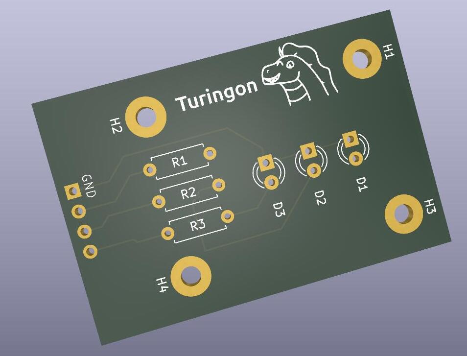
The very first tutorial was by Mathcodeprint and it was a very simple introduction, where I’ve made a small traffic light shaped component. The tutorial was very comfortable and since I liked the end result (I even added my silly mascot), I decided to go a bit more in depth and create a slightly more complex PCB that I could order.
The second tutorial was by Haus:Automation and is in German, but while it’s a bit longer, it covers all the basics including the purchase of the PCB and the pace was very enjoyable.
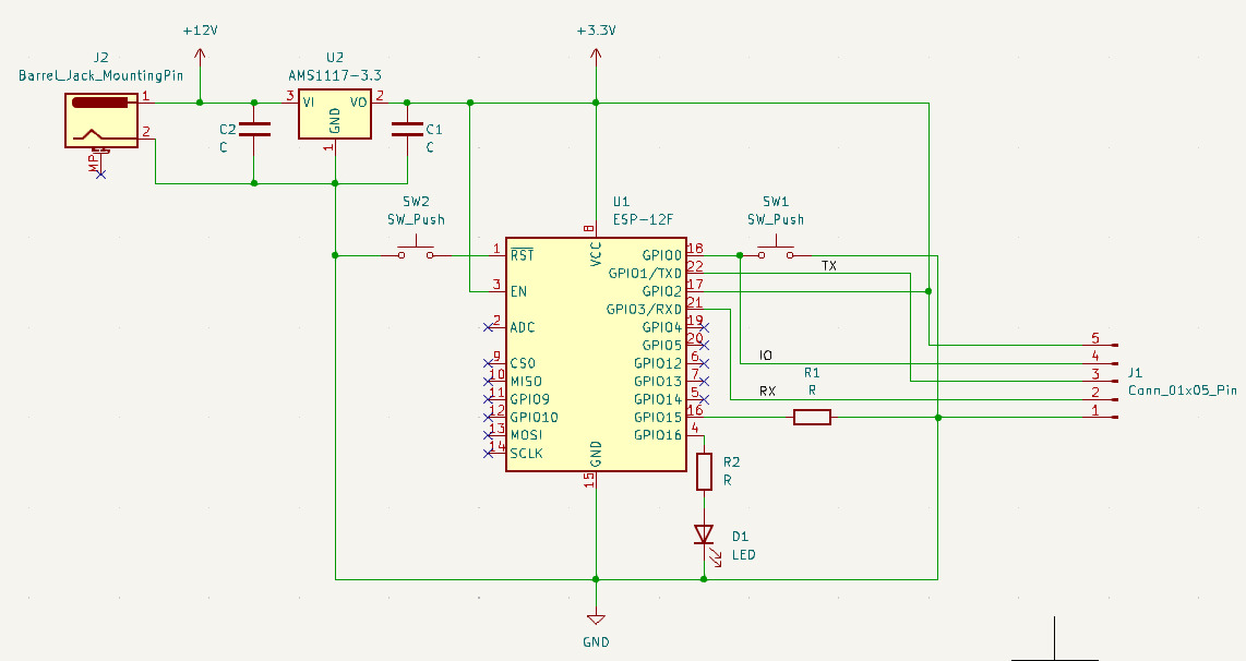
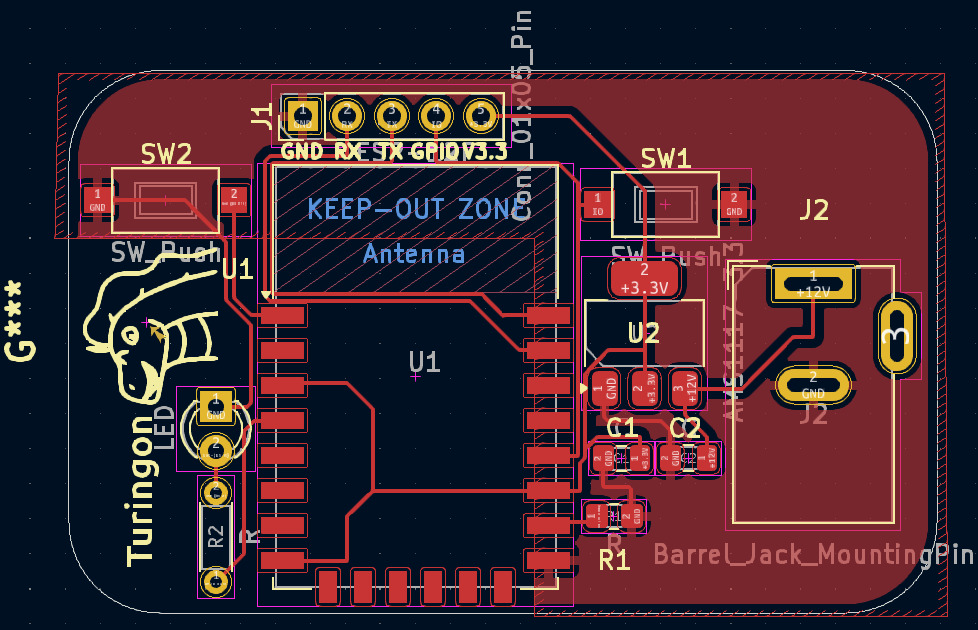
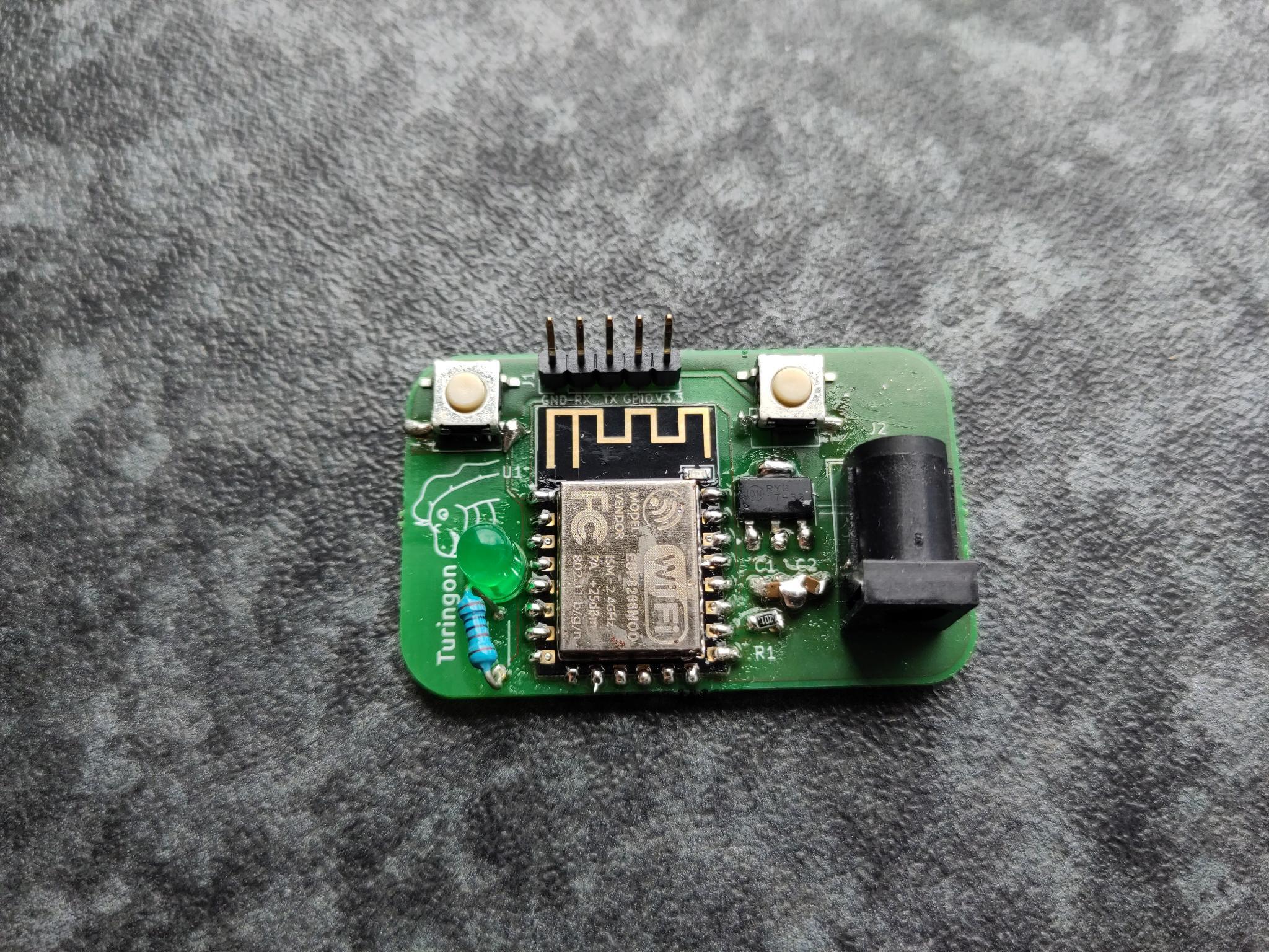
By following the tutorial I created a small ESP12-F PCB, it is programmable by UART and can be connected to the internet. It also has a LED and a free GPIO port. The PCB is thus very simple.
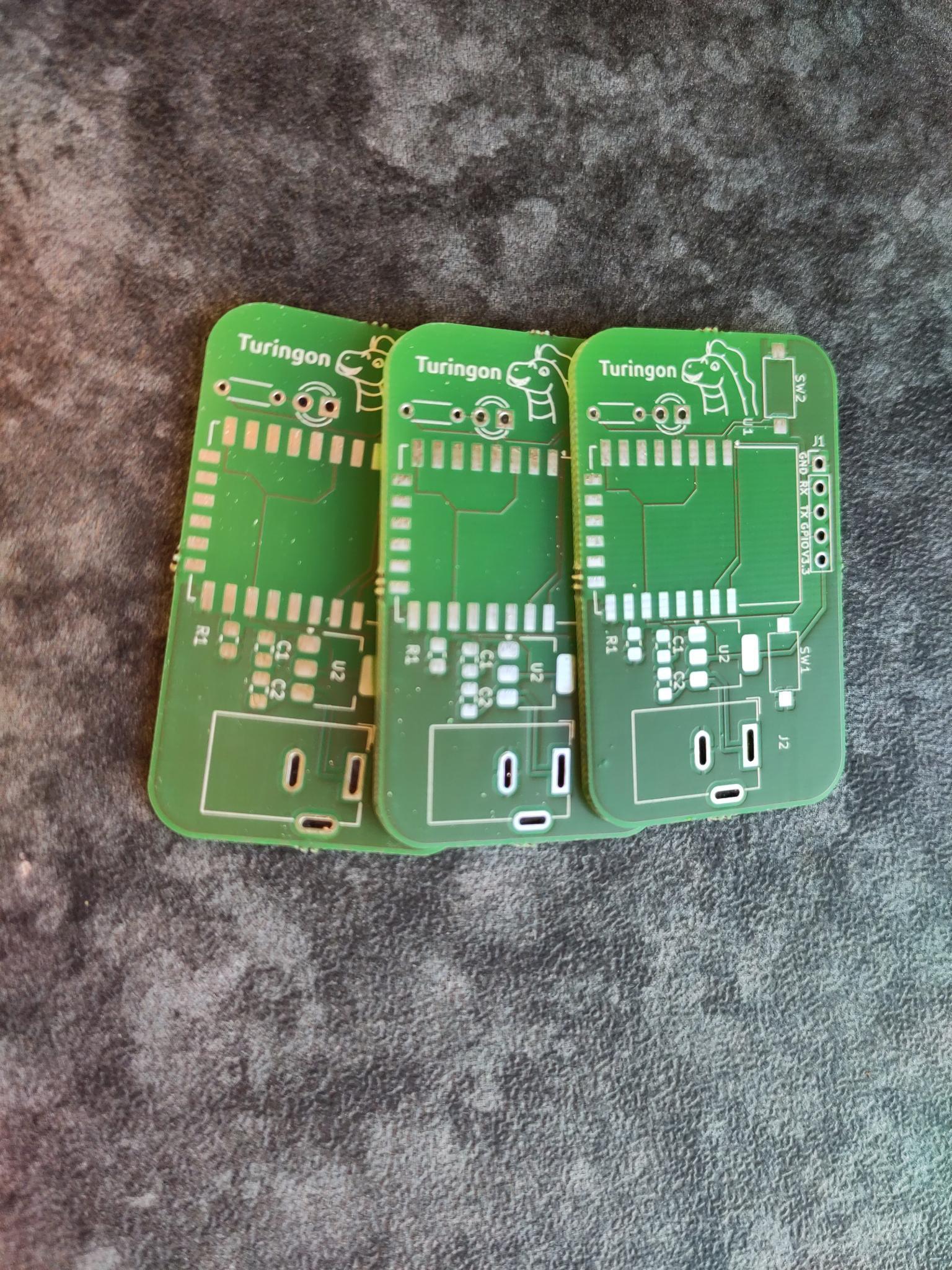
Next up I decided to produce the PCB with Aisler. I purchased the PCB on Wednesday and already got it on Saturday, even though I picked the slowest shipping option possible, which is very impressive!
I then ordered the components with Reichelt, which took quite a while, because some of them were not in stock and finally soldered them. Though I think I’ll have to take an SMD soldering course in the future and I ordered the wrong buttons, so I had to improvise.
With that I think I’m ready to design PCBs for my future projects 😁
Reply by Email